Aluminum Cable Tray Accessories
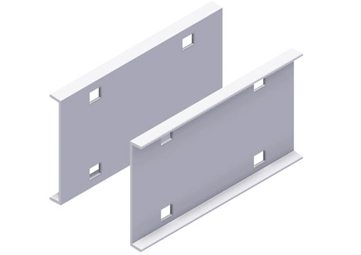
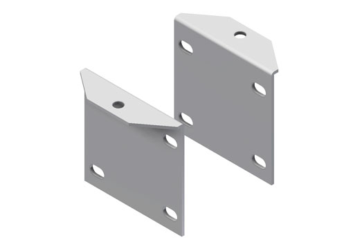
In-Line Locking Splice Plates
• Standard 4-hole pattern
• Furnished in pairs, with hardware
• One pair including hardware provided with each section
• For field installation drill 13/32” hole
| Part Number | Part Size |
|---|---|
| CM 653-4-SP-01 | 4" H |
| CM 653-6-SP-01 | 6" H |
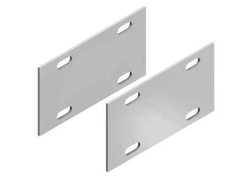
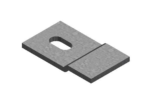
Expansion Splice Plates
• Expansion plates allow for one inch expansion or contraction of the cable tray, or where expansion joints occur in the supporting structure.
• Furnished in pairs with hardware.
• Bonding Jumpers are required on each side-rail (order separately).
| Part Number | Part Size |
|---|---|
| CM 653-4-ESP-01 | 4" H |
| CM 653-6-ESP-01 | 6" H |
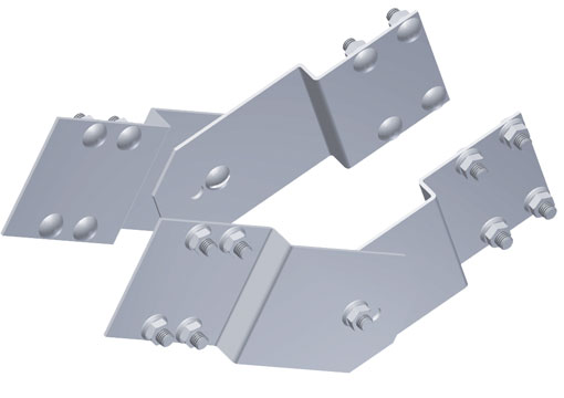
Vertical Adjustable Splice Plates
• Provides for changes in elevation that do not conform to standard vertical fittings
• Furnished in pairs hardware
• Bonding Jumper not required
| Part Number | Part Size |
|---|---|
| CM 653-4-VASP-01 | 4" H |
| CM 653-6-VASP-01 | 6" H |
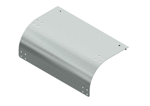
Cable Drop-Out
• These components provide a rounded surface to protect cable as it exits from the cable tray.
• Hardware is included
| Part Number | Part Size |
|---|---|
| CM 653-TO-T-06 | 6" W |
| CM 653-TO-T-09 | 9" W |
| CM 653-TO-T-12 | 12" W |
| CM 653-TO-T-18 | 18" W |
| CM 653-TO-T-24 | 24" W |
| CM 653-TO-T-30 | 30" W |
| CM 653-TO-T-36 | 36" W |
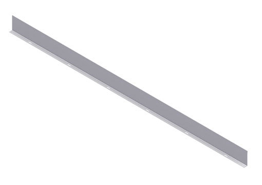
Tray Divider, Straight Section
• These components create a vertical barrier when installed into the cable tray straight section
• Furnished with three #10 x ½” zinc plated self-drilling screws
• Standard length is 60″ (5 ft.)
• Sold individually
| Part Number | Part Size |
|---|---|
| CM 653-4-DG | 4" H |
| CM 653-6-DG | 6" H |
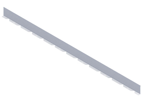
Tray Divider, Horizontal Bend
• Horizontal Bend Barriers are flexible in order to conform to any horizontal radius
• Cut to length
• Furnished with three #10 x ½” zinc plated self-drilling screws
• Standard length is 60″ (5 ft.)
• Sold individually
| Part Number | Part Size |
|---|---|
| CM 653-4-DG-H | 4" H |
| CM 653-6-DG-H | 6" H |
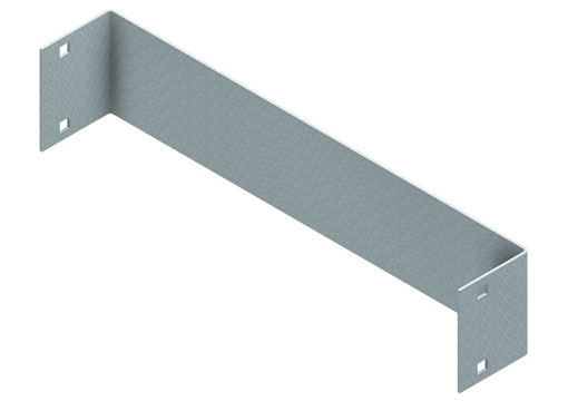
End Cap
• Creates a barrier at the terminal end on the cable tray run
• Furnished with installation hardware
• Sold Individually
| Part Number | Part Size |
|---|---|
| CM 653-4-X-EC | 4" H |
| CM 653-6-X-EC | 6" H |
X DENOTES WIDTH OF TRAY
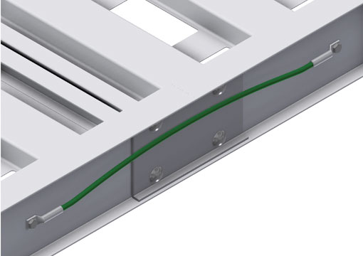
Bonding Jumper
• Use at each expansion splice and where the cable tray is not mechanically/electrically continuous to ground
• Installation hardware included
• Bonding jumper is 16″ long
• Sold individually
| Part Number | Description |
|---|---|
| CM BJ-6-8 | 6 GA, Copper, 8" Long, 55 AMPS |
| CM BJ-1 | #1 Copper, 15" Long, 600 AMPS |
| CM BJ-2/0 | 2/0 Copper, 15" Long, 1000 AMPS |
| CM BJ-3/0 | 3/0 Copper, 15" Long, 1200 AMPS |
| CM BJ-4/0 | 4/0 Copper, 15" Long, 1600 AMPS |
| CM BJ-250 | 250 Copper, 18" Long, 2000 AMPS |
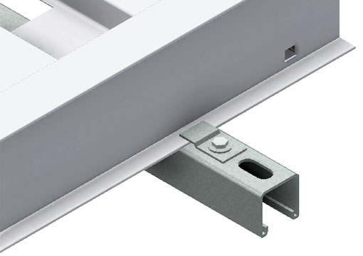
Cable Tray Clamp
| Part Number | Description |
|---|---|
| CM 653-TCK-01 | without Hardware |
| CM 653-TCK-02 | Steel, with Hardware* |
| CM 653-TCK-03 | Aluminum, without Hardware |
*Hardware
• (2) Tray Clamps
• (2) Hex Bolts
• (2) Strut Nuts
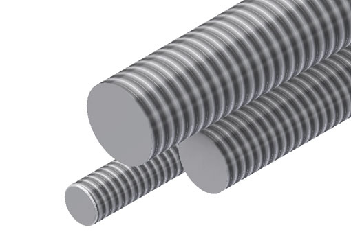
Threaded Rod
• Bonding Jumper not required.
| Part Number | Part Size |
|---|---|
| TR-1-G | 3/8" - 16 x 1' |
| TR-2-G | 3/8" - 16 x 2' |
| TR-3-G | 3/8" - 16 x 3' |
| TR-4-G | 3/8" - 16 x 4' |
| TR-5-G | 3/8" - 16 x 5' |
| TR-6-G | 3/8" - 16 x 6' |
| TR-8-G | 3/8" - 16 x 8' |
| TR-10-G | 3/8" - 16 x 10' |
| TR-1/2-1-G | ½" - 13 x 1' |
| TR-1/2-2-G | ½" - 13 x 2' |
| TR-1/2-3-G | ½" - 13 x 3' |
| TR-1/2-4-G | ½" - 13 x 4' |
| TR-1/2-5-G | ½" - 13 x 5' |
| TR-1/2-6-G | ½" - 13 x 6' |
| TR-1/2-8-G | ½" - 13 x 8' |
| TR-1/2-10-G | ½" - 13 x 10' |
| TR-5/8-1-G | 5/8" - 11 x 1' |
| TR-5/8-2-G | 5/8" - 11 x 2' |
| TR-5/8-3-G | 5/8" - 11 x 3' |
| TR-5/8-4-G | 5/8" - 11 x 4' |
| TR-5/8-5-G | 5/8" - 11 x 5' |
| TR-5/8-6-G | 5/8" - 11 x 6' |
| TR-5/8-8-G | 5/8" - 11 x 8' |
| TR-5/8-10-G | 5/8" - 11 x 10' |
Loading based on safety factor 5. Standard Finish: Zinc plated
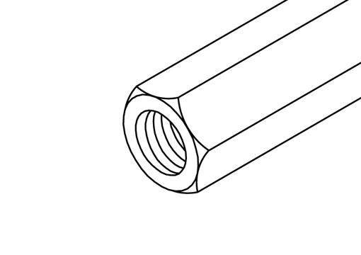
Rod Coupling
| Part Number | Part Size |
|---|---|
| CM RC-38 | 3/8" |
| CM RC-12 | ½" |
| CM RC-58 | 5/8" |
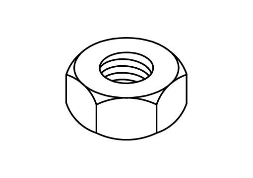
Nuts
| Part Number | Part Size |
|---|---|
| CM HN-38 | 3/8" |
| CM HN-12 | ½" |
| CM HN-58 | 5/8" |
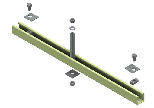
Trapeze Support Kit
• Provides the necessary components for a single trapeze support in one kit. These kits are available in pre-galvanized steel with zinc plated hardware
• The support bar provides convenient pre-punched slots, eliminating the need for field drilling
• The entire kit is sealed in a plastic bag and boxed with the channel, which is pre-cut to the appropriate length as
shown in the chart
• Designed for use with ½” threaded rod (order rod separately)
| Part Number | Description |
|---|---|
| CM 653-TS-06 | 6" Tray Width / 14" Channel Length |
| CM 653-TS-09 | 9" Tray Width / 16" Channel Length |
| CM 653-TS-12 | 12" Tray Width / 20" Channel Length |
| CM 653-TS-18 | 18" Tray Width / 26" Channel Length |
| CM 653-TS-24 | 24" Tray Width / 32" Channel Length |
| CM 653-TS-30 | 30" Tray Width / 38" Channel Length |
| CM 653-TS-36 | 36" Tray Width / 44" Channel Length |
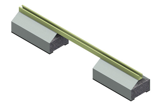
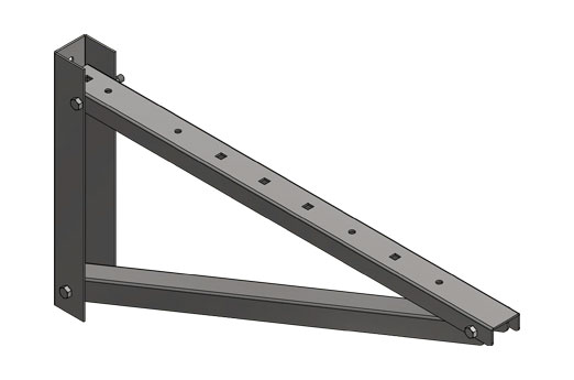
Rooftop Support Bases with Channel
• Designed for use as a rooftop support for cable tray
• Each support has rubberized pads on the underside of each leg to minimize any chaffing of the existing rooftop
• Can be used with any of Snake Tray cable tray clamps and guides
• Ultimate Load Capacity: 1,000 lbs. (uniform load)
| Part Number | Part Size |
|---|---|
| CM 653-RS-28 | 5 5/8" H x 6" W x 28" L |
| CM 653-RS-36 | 5 5/8" H x 6" W x 36" L |
| CM 653-RS-42 | 5 5/8" H x 6" W x 42" L |
| CM 653-RS-50 | 5 5/8" H x 6" W x 50" L |
| CM 653-RS-60 | 5 5/8" H x 6" W x 60" L |
Center Hung Tray Support
• Center Hung Cable Tray Support allows cable to be installed from both sides
• Eliminates costly cable pulling and field cutting of cable tray supports. Labor costs are drastically reduced
• Required hardware and threaded rod material for trapeze assemblies are reduced by 50%
• Designed for use with ½” threaded rod (order rod separately)
• Use with all aluminum and steel cable trays up to 24″ in width
• Load capacity is 700 lbs. per support. Safety factor of 3
• Eccentric loading is not to exceed a 60% vs. 40% load differential
• The maximum recommended unsupported span length is 144″/12 ft. (3.66m)
• Furnished with installation hardware
| Part Number | Part Size | Description |
|---|---|---|
| CM 653-CS-18 | 18" H | |
| CM 653-CS-30 | 18" H |
Vertical Hanger Splice Plates
• Design Load is 1500#/pair Safety factor of 2.5.
• Furnished in pairs.
• Designed for use with either ½” threaded rod. (Order rod separately).
| Part Number | Part Size |
|---|---|
| CM 653-4-VHSP | 4" |
| CM 653-6-VHSP | 6" |
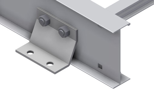
Heavy Duty Hold-Down Bracket
• For 4″ or 6″ Aluminum Cable Tray
• Design load is 4,000#/pair.
• Four bolt attachment.
• Cable Tray attachment hardware is included. Hardware to attach the bracket to the substrate sold separately.
• Recommended for support of vertical pathways.
| Part Number |
|---|
| CM 653-HDB |
